
It's the best kind, trust me.

Menu:
Links: |
My Frankenstein CNC router build.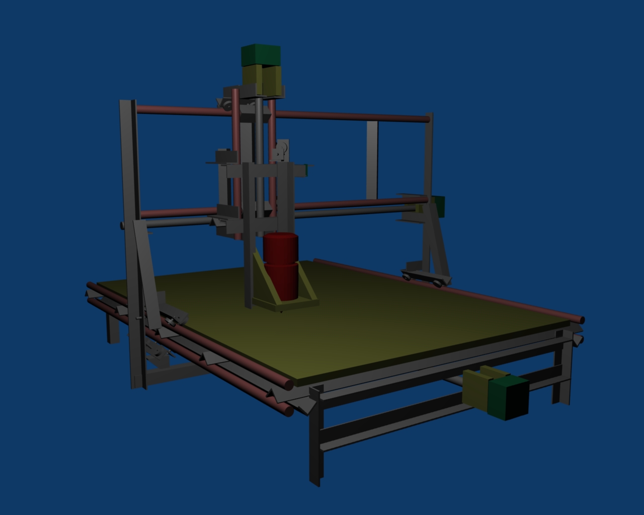 I, like many others, have decided to build my very own CNC router. I've spent time researching many websites such as CNCzone and instead of using someone else's design, I have chosen to design my own. It's not that I didn't like other designs, it is just that I didn't find any out there that used the materials I had on hand. That primarily is angle iron from bed frames. I have used this material for making bike racks and trailer hitches with my garage sale welder. Oh, by the way, most of the materials and tools I am using to build this thing is from garage sales. The table saw, drill press and bed frames have all come from garage sales or thrift stores as well. I don't expect this thing to be pretty, but I do expect it to be functional. What the heck do you do with a CNC machine anyway? Well, this thing is basically a robot. You get to tell it what to do and it will do your bidding. I figure it's a great gateway project to robot building. Also, as I don't have lots of fancy tool skills, I expect that this thing will make up for this. I expect it to be able to produce something that looks nice even when the machine looks scary. I expect to make toys for my son, toys for me, engrave things like signs, maybe engrave pictures on things. If all is working extremely well, I hope to make parts to make even more things. Design Criteria
There are some other goals involved as well. I'm a particularly horrible welder, so I expect to grow this skill during this project. I haven't touched a CAD program for a decade, so this will help. I am a civil engineer, so this mechanical stuff is not that fresh in my mind, however I do have my PE license and I'm not too bad at the engineering stuff. I hope this project will dust off the cobwebs in my brain related to engineering and materials science. I am near the beginning of the process of building this thing. My outline is as follows:
Building Has BegunWell, What I've built so far is not terribly different than my design. I'm thinking of this as a Design-Build project now. I'm building a part and then trying to figure out how it connects to the next one. The first part I built was the Y-Z axis piece. This is the piece that connects to the Y axis and the Z axis moves along. I built the Z axis rails first. This consisted of two, 12 inch sections of 1 inch gas pipe, connected to each other by two 3 inch sections of angle iron. The angle iron holds the pipes parallel. Once I got that welded up, I put together the bearings - angle iron assemblies to run along it. This was very exciting. I now had smooth linear motion on something I built! YAY! It was at this point that I noticed my first design opportunity (flaw). I now had 8 bearings riding along the two rails and it was wobbly. Somehow, I didn't see that coming. So, I figured I needed a way to make that connection tight, but allow some flex in it. I decided to make one side flexible and keep the other side ridgid. I put a hinge on one side and put a bolt with a lock washer on it to tighten it and give it some ability to move back and forth while still applying a fixed amount of tension. This worked rather nicely. The tension keeps all the bearings snugly attached to the rails at all times and the hinge has enough play in it to allow the flexible piece to move to match up with the rail perfectly. One additional thing I like about this design is that there is only one screw to tighten for the entire axis instead of multiple places that all have to be adjusted concurrently. Since I had both parts of the Z axis partially constructed (Z axis rails and Z carraige bearings), I figured the next place to go was the Y axis gantry. I put together the Y axis rails the same way as the Z axis rails using the same distance apart, but longer. This is a departure from the original design in that it is closer together than I originally imagined. Since the Z axis was so ridgid, I figured it would work just fine for the Y axis as well. Additionally, I was concerned about the distance between the cutting blade and the place where it was connected to the gantry. I wanted to make that as small as reasonable.
Once the Y axis rails were put together, I added the bearing carriage to the Z axis rails so I could run these along the Y axis. I put the same flexible connection on the carriage to the Y axis that worked so well on the Z carriage. Woo Hoo! Two axes down, One to go! It was time to build the base. At this point, the Y axis only consisted of the rails. I measured the rails to make sure I fabricated the base to match where they would be positioned. On each side of the base I fabricated the rails using the same dimensions of the other rails, except the length was longer. So, I now had two sets of two rails held apart by three inch angle iron. Then I cut some angle iron to make a rectangle to attach them to. I used great care with the square to make sure they were 90 degrees from each other and welded it all together. Then I put on stubby legs to keep it off the table. At first, I put three legs on, but that was a mistake. I have now added extra legs to make it very sturdy. Once the table was built, I added legs to the Y axis rails and attached yet more bearings to each foot. Now, the gantry was taking shape. I could put the Y axis on the X axis table and have the thing stand up. I then put the Y-Z axis piece on there and the final shape is coming together. The next thing I did was monkey around with the Z axis carriage. All I had were the bearings and angle iron held apart by a piece of angle iron. I needed to figure out how I was going to hold the router on there. It's a bit of a kludge but I added some angle iron pieces and diagonal support pieces to make the router connection sturdy. I can now slide the router in and tighten it up with the ring around the base of the router. Unfortunately, since I didn't finish the bottom of the Y axis gantry, I can't put it all on there without the gantry flopping down. One other complication has arisen regarding the Z axis. I originally envisioned the motor for moving the Z axis to be centered between the Z axis rails offset toward the router. Well, in an effort to decrease the offset distance to the router's cutting head, I've built the Z axis carriage in such a way that the original mounting location for the motor will not work anymore. I'm planning on now putting the lead screw and motor off to the side of the Z axis rails. Since I already put the motor mounts on the Z axis rails, I will have to remove them and put new ones on. At this point, I am toying with how I'm really going to mount the motors and lead screws. I've drilled some holes in a chunk of angle iron and placed the lead screw through there. Along the lead screw, I've put a Nut, Washer, Bearing, angle iron with holes, Bearing, Washer and Nut. This assembly, when tightened, will allow the lead screw to turn while the angle iron piece stays stationary. There are some catches though. The first is that there is a lot of resistance to turning. This does depend on how tight you make the outer nuts, but you have to make it tight enough to not come loose. This was a concern because I am using Skate Bearings, which aren't meant to be loaded this way and I don't know how strong my motors are just yet. The second concern is that my lead screw is not straight! When it turns, the angle iron wobbles. Maybe that is normal when you use a common thread from the hardware store. Well, I decided to go forward with what I had, so I welded the angle iron to my gantry and used my cordless drill to move the long nut along the screw. This was pretty fun, but it did make the lead screw wobble quite a bit. Once I welded a tab onto the Y-Z carriage piece to connect the long nut to ( and zip tied it on ), the wobble quieted down a lot. Now I can use the drill to move my carriage back and forth. This is a big milestone. I will have to support the far end of the lead screw at some point though because I am worried about the wobble as the Y-Z axis carriage piece gets close to the fixed end of the lead screw leaving a long piece of screw hanging off into nothingness. Next up: Non-Zip-Tie connection for the Y-Z carriage, Undercarriage for the gantry, X and Z axis lead screws, motors and such...
|